Zilla FAQ


Zilla FAQ22 Sep 2010 09:41 am

Recently Shawn Lawless posted some comments about “thermal events” aka a controller blowing up and I realized that this is something that everyone installing a controller should really consider since this is a major safety issue.

Controller thermal events can happen on any EV running any controller. Fortunately Zilla controllers have been very reliable and failures have been rare. Unfortunately this means that most people are not familiar with what a controller thermal event can do. Now that many Zillas are passing the ten year mark (and some 15 years) and people are pushing them harder than ever we can expect more units to fail.

So what’s it like when a Zilla fails at full power? Sometimes it’s only a small pop and a little smoke leaks out. Other times it can mean a severe amount of explosion, fire and plasma. Remember what the carnage looks like on those old C type 1221 controllers that used to blow rather often in the 1990s? Those 120V 400A units that we used to think had power!? Maybe you were not playing with EVs then but I remember end covers blown off and flames shooting out the end, molten copper and aluminum dripping off the ends. Burnt paint and lots of carbon was common. Well, you can take that mess of flame, molten metal and carbon and multiply it by about ten for a high power Zilla setup. Forceful plasma balls can melt through plastic covers like there was nothing there and burn sheet metal shields enough to roast the paint on the other side. Preparing to minimize such an event is essential.

My point in all this?
Be prepared and don’t let this potential failure cause injury. Here are a few tips to consider when installing a controller:
* Never install a controller power section in the same compartment with the driver or passengers.
* Consider what would happen if a large ongoing fireball where to shoot out of the end of your controller. Would your vehicle still be safe?
* Be very careful to use the correct size semiconductor fuse in the battery circuit. This will have a lower current rating than the controller, usually less than half the peak rating of the controller. Be sure to use the fuse I/T curve to select the smallest current rating that will do. The fuse must also be rated to break the maximum DC voltage of your system at full charge. AC ratings are not enough.
* Always use a safe main contactor rated to carry the maximum expected current for the required duration without welding on, and then to break the maximum possible fault current. On a Zilla this will allow the Hairball to do it’s job and quickly shut off power in case of a failure. Beware of the continuous ratings of Kilovac and Gigavac contactors. I think they are deceptive in that they rate them with absurdly large cables attached to cool the terminals. If you don’t have those large cables, the contactors will weld on at those “rated” currents. They often do not list ratings for the smaller 2/0 cable we often use on the battery loop.  See my Faq for more on contactors.

EV’s are a lot of fun and games until someone gets hurt. Please, let’s be safe out there!

-Otmar

Zilla FAQ02 Oct 2009 01:27 pm

Q: Now that I have the car running with the Zilla, how should I adjust the battery and motor settings?

A: In general, higher current produces more heat in the batteries, motor and interconnects. Most failures in EV’s are caused by too much heat buildup. Adjusting the limits that are stored in the Hairball can help prevent premature failure of your EV.

We ship the Zilla package set for wide open full power operation. While this is good for making sure it runs right out of the box, it will usually destroy parts of your car if adjustments are not set correctly.

Please note that the Hairball has a “Valet” mode that allows you to quickly switch between two sets of settings on the fly. See the owners manual for more detail on where to connect a valet switch.

Before setting current values, insure that option ‘p’ in the Options menu is ‘on’ if you have a Z1K and ‘off’ if you have a Z2K. Changing this setting will change the set values for current limits.

Be aware that although Hairball settings are close, they are not very precise. It is always good to check the effect of the adjusted settings with a meter while driving since some settings (especially the LBV) will start limiting a bit before the actual set voltage is reached in order to provide smooth response.

Hairball settings all limit maximum and minimum values. This will help prevent failures to a large extent but since there is no feedback from the various temperatures on the vehicle there is no way to insure that damage will not happen from extended operation below the peak limits. That protection needs to come from the vehicle design on lower performance vehicles, and proper instrumentation and operator awareness in higher performance vehicles.

In this article I am assuming the most common street EV conversion setups. Suggested values should be tailored to your components. Unfortunately good data is often hard to come by, therefore it may require instrumentation and tests to determine safe limits.

Battery Menu:

In most EV’s, batteries are the weak link. If you draw too much current from the batteries and in the process of drawing that current the voltage sags too low, the batteries will be damaged. If the draw is much too high the internal connections in the battery will melt and the batteries can blow internally or explode. Drag racers are used to running near these limits and likewise do not expect to get long life from batteries. If your current draws are high, but not so high as to cause catastrophic failure then there is still the risk of greatly shortening the life of the batteries by abusing them with high currents and deep discharges. This is why it is important to set limits for your particular setup. Higher power batteries, those with low internal resistance, will tolerate high current draws better and last longer while putting out high power. Low power batteries such as the flooded golf car type or large format low power lithium cells can provide low cost of ownership but can not supply high power without risking damage. The Zilla has three settings to help protect the batteries. How you set those settings depends on how much power you require and how much battery life you expect.

The first setting in the Battery Menu is “Battery Amps”. This is a limit on the current that the Zilla will draw from the batteries when other conditions permit. High values here can damage your batteries but also can directly relate to higher power. Racers will often run this value as high as possible while street cars are set lower. A car running golf car batteries would run this in the range of 300 to 600 Amps while a racer running AGM or high power lithium batteries may run it between 1200 and 1800 amps. If your battery voltage limit is set high, then the controller may never reach the battery current limit before the voltage limit becomes active. Battery current never exceeds motor current, so if your motor current limit is lower than the battery limit the motor current will be the limiting factor.

The second setting in the Battery Menu is “Low Battery Volts”. The controller will automatically reduce the output current so that the battery voltage does not run below this value. This is a very useful setting for obtaining maximum power when racing and also for protecting batteries in normal street use. A very conservative setting for this is obtained by multiplying your nominal pack voltage by 87%. If your pack consists of 13 batteries that are 12V each, then you have a 156V pack and a very conservative setting would be 136V. A more common setting to insure reasonable power is 75% of the nominal pack voltage, this would be 117V for a 156V nominal pack. For those looking for absolute maximum power from the pack, that can be obtained at 55% of pack voltage, but beware that this will produce massive heat in the batteries and likely will cause failures. The Zilla may limit battery voltage as much as ten volts above the set value depending on the motor current so be sure to verify this value with a meter while driving under load and adjust it as needed to meet your target.

Be aware that LBV only sets the minimum pack voltage. It is likely that the battery pack will not be perfectly matched and so a weaker cell will fall below the average cell voltage. People generally set settings more conservatively in order to account for weaker cells.

The third setting in the Battery Menu is the Low Battery Voltage Indicator. This setting determines at what pack voltage the dash battery light turns on. The battery light on the dashboard should be connected to the ‘Battery Lt Out’ on the Hairball. This is a very helpful simple indicator for showing the state of the battery while driving. I like to set the LBVI value at 87% of pack voltage, or just slightly above the LBV setting, whichever is higher. That way it is easy to see when the battery is being stressed by low voltage. If this light starts coming on during light acceleration then it is clear that the pack is at a low state of charge or has a problem.

Motor Menu:

Motor current is proportional to motor torque. Naturally, high current is desirable for high power. Higher current also produces much more heat. As with many circuits in an EV, it’s handy to remember that the heat produced in Watts is equal to the current in Amps squared which is then multiplied by the resistance in Ohms. Assuming the Ohms are constant, doubling the current quadruples the heat produced. Series wound EV motors generally fail from heat in two areas. Winding heat can get hot enough to melt the polyester insulation when the motor is slightly overloaded for a long time. Also brush and commutator temperatures can quickly overheat and damage the commutator within seconds. Brush temperature rises quickly with high current levels and especially quickly if the motor voltage is high enough to cause arcing or flashover at the brushes. Major brush flashover from excessive motor voltage often makes itself known with a bang that sounds much like a backfire in a ICE vehicle. In case of a flashover, it is imperative to inspect all the bushes, springs and surrounding area for damage before continuing to drive.

Racing EV’s and single ratio street machines should be equipped with at least one brush temperature gauge with a 230 deg C redline. A piece of cheap fiber optic cable pointing at the trailing edge of the brush which is visible in a dark tube on the dash can do wonders for monitoring brush arcing.

For a typical street conversion running a 8″ or 9″ motor, I run the motor current limit between 500-600 Amps. Higher than that often results in a slipping clutch and increases motor heating as well. I have tested Advanced DC motors in 8″ and 9″ sizes in standard and XP models and have found that with perfectly broken in brushes in race situations the motor voltage can be set as high as 170 Volts without causing flashover. In street applications I suggest limiting them at 150 Volts. Other motors may have different limits, but I have seen little actual test data on them at high voltages.

Reverse settings become active when there is power connected to the ‘Reverse Input’ on the Hairball. Amps should be set high enough to allow enough torque to back out of a steep situation and reverse volts can be set low in order to limit reverse speed.

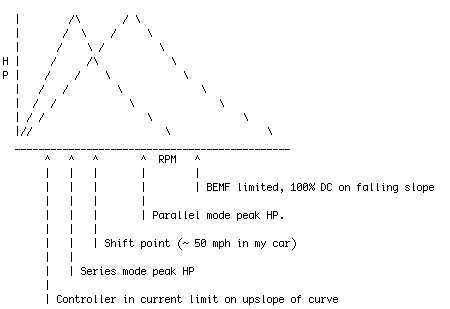
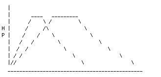
Parallel settings are only used in dual motor setups that are wired for S/P switching. Parallel is normally used at high speed to get extra power. Usually this happens over 40 MPH on single ratio direct drive vehicles. The limits set in the Hairball are what the controller supplies to the motor circuit, so if you want to limit average motor current of two motors in parallel to 800 Amps, then the parallel setting should be set at 1600A. To limit the average voltage of two motors in series to 150V, the standard series voltage limit should be set to 300V.

Speed Menu:

Speeds are a simple and abrupt limiting value. The normal and reverse limits should be set low enough to protect the motor. The ‘Max’ setting does not limit speed by itself, it only logs a error so that one can tell in the future if the set speed was exceeded.

-Otmar

Zilla FAQ02 Oct 2009 01:03 pm

Q: How to protect the Hairball while wiring the car?

A: Remove all power to the Hairball before performing any wiring. Double check your wiring before powering it up. Also, be sure you have the correct snubber diode (supplied with the unit) installed on the contactor before turning it on for the first time. Beware that the snubber diodes supplied by Albright are not acceptable.

The two most common repairs that require return to the factory come from shorting Hairball outputs while wiring the car and neglecting the proper snubber diode on contactors. Some compromises were made in the Hairball 2 design in order to keep the cost well below the $800 that is typical of automotive ECU’s. Primarily this means that the Hairball is not tolerant of shorted outputs and reversed power applications. If your Hairball is damaged due to improper wiring it is imperative to remove all power since sitting damaged with power applied can further damage the unit sometimes burning the PC board beyond repair.
If you suspect a problem due to fuses blowing contact the factory for repair.
Shorting of the speed sensor power lead can cause also the Hairball to be damaged. In that case it will report a 1131 error and not start up. If at any time the voltage on ‘Acc +14V Out’ is well below the ‘SLI +14V In’ then the unit needs to come back to the factory for repair.

Usually these problems are not expensive to fix if caught early enough. Contact the factory to get a RMA number if needed.

-Otmar

Zilla FAQ15 Apr 2009 05:59 pm

Q: Why does the Zilla cut out above 450 Amps? I have the speed sensor on the Warp 9 motor connected to the Hairball. When I turn on option (a) for single motor speed sensor the Hairball shuts down the input when I accelerate  past a about 450 amps. I then lift up the pedal  and it resets and works again just to cut off again as soon as press past 400-450 amps. I turn off the speed sensor and works fine.

A: Electrical noise on the speed sensor signal sometimes causes the Hairball to shut off power since the noise cancels out the speed sensor input pulses and makes the Hairball think the motor is stalled. If that is the case, turning off option “d” would also make the problem go away. If you hook up your tachometer to the Hairball I believe you will see it drop to zero at high currents or whenever the problem is happening.

Sometimes this can be fixed by better routing of the speed sensor wires relative to high voltage and high current wires since they are the ones picking up controller switching noise.

Another fix that always seems to work is adding a 0.1uF ceramic capacitor* to the speed sensor power wires (red and black) right near the speed sensor. I suggest connecting the capacitor no farther away from the sensor than the connector that came on the sensor.

* The capacitor can be almost any type, Radio Shack PN 272-135, 272-1069, 272-1053 are all acceptable.

I hope this helps,
-Otmar

Zilla FAQ07 Aug 2008 10:06 pm

Q: Do your controllers work with Brushless DC / BLDC or AC Induction motors / ACIM ?

A:  No. The current Zilla controllers only work with brush DC motors such as the series wound motors that are used in most EV conversions.

I have made BLDC and Induction AC controller prototypes in the past for special projects, but will not pursue production designs until I feel the time is right, and I have the resources to do it. If you feel the time is right, and have over $1M handy for expediting the process then we can talk. If not, please don’t bother me or I’ll just send you a rude response of some sort for wasting time.

-Otmar

Zilla FAQ07 Aug 2008 09:32 pm

Q: What’s that sound when I start driving?

A: People variously report hearing a scraping, hissing or even sometimes a hum when they are driving slowly with a Zilla. This is perfectly normal for a Zilla powered EV and is not likely to be your driveshaft scraping on the body (though it could be that).

Due to speed limitations of high power electronic switching devices it is necessary to modify the pulse width modulation (PWM) of power devices in a way that has audio consequences. We could have made it squeal like some other controller manufacturers did, but decided that we found white noise more pleasant.  This is a noise made by the motor in response to the spread spectrum frequency modulation that it receives while the Zilla is in current limit. Since it happens while in current limit and when the motor voltage is very low this sound is usually only heard when the motor is turning slowly. The speed range over which it makes the sound is more pronounced in both single ratio and high voltage vehicles.

-Otmar

Zilla FAQ14 Jul 2008 09:52 pm

Once every 50 controllers or so we hear of someone having a problem with rough or jumpy starts on a Zilla. Since this just came up again, I figure I’ll write a FAQ about it.

First off, the Zilla is designed to be a very smooth controller. Rough starts are not normal. Your foot, the motor, drivetrain, potbox and controller make up a large dynamic system. The complexity of the system sometimes makes it hard to figure out what is causing the system to be rough. I will go over the problems starting with those that are most common and ending with those we rarely see.

1 ) Starting in first gear:

In most EV conversions first gear is never used. When the torque load on a motor is small due to the low gearing, and the difference in motor current between no load and normal load on the motor is only a few amps, then the inertia of the motor overpowers the flexibility in the drivetrain (motor mounts, axles, tires etc) and it is hard to get a smooth start. In this case the smooth motor current control of the Zilla can’t help you much since so little current is involved. Unless you have a unusual configuration you should not use first gear at all.

2 ) Lack of proper return springs on the throttle assembly:

All vehicles should have two return springs where each one is capable of returning the pedal by itself. This is not only a good idea for safety, but reasonable pressure on the accelerator pedal resists the tendency of your foot to be jostled during acceleration. A pedal that is too light will cause rough starts. And no, the return spring that comes on the Curtis pot box is not enough by itself.

3 ) Lack of an accelerator cable.

It is common to think that low drag is better, but this is not always true on the accelerator pedal. Running a pedal with a rod linkage, that is, without a cable, causes two problems. First of all the lack of stiction makes the above mentioned bouncing foot problem worse when starting off. Secondly the fact that your foot is always shaking a bit wears out the pot right in the part of travel that is used while cruising down the road. So just a bit of stiction in the system is a important trait to design in.

4 ) Bad/Worn/Defective Potbox.

The potboxes that are currently available are of poor quality. I have seen a number of brand new ones recently that do not smoothly transition near the beginning of travel. This can be checked with a meter set for reading ohms while you slowly move the pedal through it’s range. Although it is easier to see this with an analog meter, it is still common to miss a problem internal to the pot since it only takes a small jump to make the car surge. Sudden jumps in resistance when smoothly moving the pedal indicate a problem. Sometimes replacing the pot (maybe temporarily with a rotary pot that is not affected by foot feedback issues) is the best way to rule out other causes. The pot input can also be tested for smooth response using the DAQ 4 to read the value as described in the owners manual and other sections of the FAQ. The first value of DAQ 4 represents the potentiometer reading in a hexadecimal format. The pot input will be read by the Hairball even with the key off, so there is no need to turn on the high power contactor to do this evaluation. If the roughness started happeing after some time, and especially if it is in cruise mode then it may be a dirty pot. A quick temporary fix is to stomp on the accelerator five times (with the key off!) and then go out for a drive and see if it is resolved. If this fixes it then there is a good chance that your pot is on the way out.

5 ) Poor potbox mounting:

The potbox should be firmly mounted to a area of the car that does not change position with motor torque. I have seen situations where a potbox mounted on the motor assembly, with a cable that was not quite flexible enough, would cause the torque reaction of the motor to feed back into the pot position.

6 ) Loose motor mounting:

A motor with very sloppy motor mounts or one that is missing a torque bar (when the car was originally designed to use one) can cause oscillations in the drive system.

7 ) Corrupt Hairball settings.

There is a factory testing setting that disables the smooth current control on startup. If your Hairball settings were ever corrupted for any reason (this would be indicated by a 1113 Error unless the error count is over 5) then it is imperative that you reset the defaults using the special menu and then re-enter your desired settings. If there is any doubt, then I advise trying this fix first since it is such a easy fix.

8 ) Bad solder joint in inside the Hairball.

We make errors in production too, occasionally we don’t catch them before shipping. It is not common, but we did have one case years ago where the filter capacitor for the throttle input was not soldered down properly. If you suspect this problem, contact us to get a RMA number so you can send you Hairball back to the factory for inspection.

9 ) Poor pot box wiring or connections:

I put this last since the Hairball is very unlikely to react to potbox wiring noise (I tested the design by wrapping a potbox cable around the M+ motor lead) but it is possible that the wiring connections are loose, or that someone did not use the standard twisted pair wire that comes with a potbox and decided to make an antenna loop out of the wiring instead.

As a side note, roughness is much less common when using our HEPA pedal option since it eliminates quite a few of the common issues causing this issue.

I hope this helps,

-Otmar

Zilla FAQ29 Apr 2008 04:20 pm

I’m confused- how does the series to parallel switch happen and how does it enhance motor power and amp consumption?

Thks
Rush
Tucson AZ

Hi Rush,
Here is a snippet from the EV list some time ago. I’ve tried to edit it a bit for clarity.

EVList Post from 2004 follows:

OK. Let’s think about this a bit. Why did Otmar chose to shift at
1/2 the peak amps (and are we talking battery or motor amps,
anyway?)?

Let’s assume it is *motor* amps that determine the shift point. When
the motor amps drop to 600A in series mode, and the controller shifts
to parallel, the motor amps stay the *same* provided there is enough
battery voltage available to push the controller back into current
limit. RPM doesn’t change instantaneously, so there is no stair step
in power; the shift to parallel just makes full pack voltage
available to each motor so that they can continue to build speed
while amps/torque continues to fall off.

I know Otmar is trying to follow this thread, so perhaps if I haven’t
put him to sleep already he can chime in with a proper explanation of
how/why the ‘Zilla implements series-parallel shifting…

Otmars Response follows:

I should mention to the uninitiated that this shifting involves utilizing the Hairball to drive contactors switching two motors electrically from series to parallel configuration. It is sometimes used in dual motor cars when trying to get the best acceleration out of a system while avoiding the higher cost of buying two controllers. It is mostly used with Z2K’s since high voltage Z1K systems do not gain as much unless the batteries sag quite a bit under load. In series mode the two motors can see up to half of the available battery voltage (don’t forget to take into account battery voltage sag) and each gets the full motor current. In parallel mode the motors can each be supplied with up to the full battery voltage but each gets only half of the available current from the controller. Parallel mode can allow both motors to draw more power when they are spinning at higher RPM.

The operation is pretty much just as you said. Initially I had the shifting happen at a certain adjustable RPM, but that’s inefficient on the street and does not compensate for battery temperature and state of charge, so I devised the auto shift algorithm and left the option of a manual shift for those who want to experiment.

When the Hairball is set to Autoshift mode it works like this:
It starts in series mode for maximum torque and for lower controller current in regular driving. Then, when you put the pedal to the metal the Hairball starts to pay attention.
In order to initiate a shift to parallel, the first requirement is that the controller is at 100% duty cycle. (this is the right side of the mountains shown below) This means the controller is full on the battery amps equal the motor amps. If the controller were still acting as a transmission then there would be no reason to switch the motors yet since the resulting power would be less after the shift.
After reaching 100% duty cycle, the motor and battery amps are dropping as the vehicle speeds up.

A simple way to view the HP to RPM curve of a series motor in a EV is to imagine it as a mountain. The upramp of the curve is the controller in current limit, the downslope on the high RPM side is when the controller is full on and the motor BEMF (Back Electromotive Force) is limiting power.

In order to maximize the power under the curve, I believe you want to shift when the falling series curve of motor power vs rpm crosses the rising curve of the motors in parallel. This turns out to be when the series mode current is half of what would be available after the shift.

Here’s a bit of ASCII art.
View with fixed width font like Courier.

Series Parallel Shift Standard

By the way, it’s interesting to note that these curves look same as the power curves seen when shifting a mechanical transmission. The big difference being that with a mechanical transmission the loads on the motors and controller are lower and so mechanical shifting is usually preferred.

Just FYI here are the same curves when the battery current limit is lower than the motor current limit. The lower the battery current, the less important the actual shift point timing becomes.

Series Parallel Shift Battery Limited

I hope this helps
-Otmar-

Zilla FAQ07 Apr 2008 08:59 pm

Recently there have been a larger than usual number of people asking questions well beyond the usual “My car is a A, weighs B and has C components, which Zilla is the best one to use?”.

If you have been directed to this FAQ entry by our support department, then we did not have a simple answer to your design question. We are, of course, happy to answer questions about our product for those who buy direct from us, but have to limit our time expenditures for questions beyond that so we don’t get even farther behind on our production schedule.

As much as we would like to, we can’t help everyone design their EV conversion. Unfortunately, Cafe Electric llc. does not have the engineering resources available to guide the many people who are looking for help with basic vehicle design at this time. It takes significant resources to do this well; time spent in discussion with the user, calculations, and maintaining the ever changing knowledge of which components are available. There are at least a few people that we have heard of offering help with the design of EV conversions for a fee, but not knowing the quality of the offerings they will remain nameless at this time, let the seeker beware.

Here at the Cafe Electric llc. web site, we are attempting to build information resources that will assist people to make their own choices concerning the best combination of components. At first it will all be listed in this FAQ section. It is a slow process. As it grows we hope to find time to put it in a framework that we have for comparing the merits of various component options. This of course can never be fully complete, but we’ll endeavor to improve it gradually as our resources allow. In the meantime we will try to focus new FAQ answers on those questions that we see the most and feel are most important.

Many other resources are useful for designing an EV. We have a “Links” page that lists some valuable resources among which are: The EV List, an excellent place to ask specific questions. The EV List Photo Album, also a great resource since you can see what those who have gone before you have used in similar situations. The EV calculator is decent for constant speed calculations and rough estimates. The motor curves maybe based on the flawed formulas in the “build your own EV” book, so I never use the motor part of the calculator much.

Beyond that, there are many resources on the web. If you find a particularly useful one, we would appreciate hearing of it so we can add it to our links page.

Best of luck with the research!
-Otmar

Zilla FAQ12 Mar 2008 11:19 am

Batteries are a difficult issue. Battery choice is probably the single most defining choice that determines how your car performs and what it will cost to drive. Estimating the battery replacement cost as it works out in a per mile format is a important part of the battery choice for most people with limited budgets. My 914, which is raced and whose batteries are often abused, comes out close to 50 cents per mile in battery cost while the wind generated electricity for it costs only 3 cents per mile. I suspect that many people would consider my battery cost too high for a commuter car.

In addition to up front costs, there are many other variables to consider when choosing a battery type and configuration, here are a few important ones:

How many cycles will the target battery be expected to last? It is often difficult to get data for estimating this, but it is important to consider how your planned power draw levels and depth of discharge (DOD) will affect life. Sometimes finding someone with experience in a similar application is the only source of information. The answer to this along with your expected normal driving range will allow you to determine your battery replacement cost per mile.

Will your target pack capacity fit in your vehicle? Capacity on lead acid batteries is closely related to weight, so I suggest estimating your target battery pack weight and going from there to see what voltages various options would provide. Or, if a small pack is your target such as with lithium cells, then I suggest you start with your required capacity in kWh and make the weight a less primary concern.

When figuring out how much battery you will need, be sure to consider the “C” Rating of the capacity. A battery will supply much more energy at a 20 hour rate than it will at a 1/2 hour to 1 hour discharge rate more typical of EV’s.

Battery pack voltage has little direct effect on vehicle range. A 1000 lb lead acid battery pack with 144V will have a very similar range to a 288V pack of the same weight. Lower voltages such as 156V and under can be easier to use since safety devices like contactors and fuses are easier to find and controllers cost less, but higher voltage systems can get more power out of our currently available motors. In general, speed costs money, and higher voltage gives higher speed.

Will you be able to end up with an acceptable pack voltage when you have put in your target weight of batteries? This is primarily determined by the weight and voltage of the battery module. In some cases people will run more than just one series string of batteries opting for multiple parallel strings or batteries in “buddy pairs”. You should be forewarned that this makes cell equalization tricky and so may impact battery life.

Do you need maintenance free batteries? They generally cost more per mile, but often give more performance (power in AGMs, life in Gels) as well.

How much power do you need? Will gel or flooded batteries provide enough power or do you need the higher horsepower of AGM (or maybe high power lithium) batteries?

There are thousands of batteries available, most of which are not regularly used in EV’s. In general I suggest finding a battery that someone has used in a similar application for several years with good results, since the sales literature is often misleading or optimistic on a batteries capability. A good place to look for such a person might be on the EV List where there are many people running EV’s and in the EV List Photo Album. You can find links to these on the Cafe Electric links page currently located under “Other Info”.

When comparing battery specifications it is helpful to keep in mind the quote often attributed to Thomas Edison:
“There are liars, there are damn liars, and then there are battery salesmen.”

-Otmar

Zilla FAQ02 Mar 2008 07:06 pm

Many computers these days are sold with no RS-232 serial port. The Hairball requires a standard RS-232 serial port and any flavor terminal program in order to set settings, retrieve error codes, collect data and update firmware if required. All except the firmware update can of course be done with the Palm Pilot handheld computers that I sell pre-configured, but naturally people with laptop computers would rather use them.

I suggest that people who do not have a serial port built in to their computers obtain a serial to USB adapter such as this one made by Keyspan. USA19HS

There are cheaper units available that seem to work well once they are set up, I like the Keyspan one since it has worked well for me and was easy to set up on Macintosh and Windows computers.

For more more details, please see the section titled “Using a Computer to Communicate with the Hairball” in the Hairball owners manual.

People often ask why I didn’t integrate USB directly into the Hairball. This would be equivalent to installing such an adapter inside the Hairball. Unfortunately, terminal programs do not work directly with USB adapters and it becomes necessary to install drivers in your computer in order to recognize the USB port as a communication port. The primary reason I avoid that is because operating systems are constantly changing and I don’t want to take on the responsibility of supporting computers. It would add “software provider” to my support duties and I don’t want to dilute my efforts on things so weakly related to EVs. With the external USB to serial adapters, driver and support issues are handled by the manufacturer of the adapter.

-Otmar

Zilla FAQ25 Feb 2008 11:30 pm

Q: Does the Hall Effect Pedal Assembly (HEPA) fit my car?

A: I don’t know.

The HEPA is a wonderful pedal assembly. It is rugged and smooth, but it will not fit well in all cars. You will have to examine the pictures (taken here with a 6″ caliper for reference”) to get an idea. Or you can order one to check the fit, if it does not fit well we will cheerfully take the undamaged unit back for a full refund and change your Hairball to a standard Pot input version.

Some cars have been proven for a good fit, I will list the ones I know of here. If you have pictures and a description of a car that it did, or didn’t fit well I would appreciate hearing about it so I can add them here.

The Corbin Sparrow.
Bob Schneeveis reports to me that the HEPA “looks like it was made to fit the Sparrow”. I have not seen it myself, but I believe that he made one fit with only a couple new mounting holes.

The Honda Insight.
I have put a HEPA in my Honda Insight conversion and it fit perfectly. It did require drilling two new mounting holes and putting rivet nuts in them, then one aluminum spacer later and I had a perfect fit. See the following pictures for details:

Hoda pedal 1

The original pedal, side by side with the HEPA.

Insight pedal 2

The two golden plated parts are the mounting threads that I added. The top one required a aluminum spacer to bring it level with the mounting area. Rivet nuts, metric bolts and spacers all came from McMaster Carr online.

Insigth pedal 3

In place the pedal is a perfect fit for the Insight.

Porsche 914:

Richard Rau of Northwest Electric Vehicles did a wonderful job of integrating the HEPA into a 914. It was not as simple as the Honda Insight, but the results are very nice. The pedal can fit in the 914 with just a simple bracket, and I have done this before, but the resultant pedal alignment ends up being less than ideal. Richard, being determined to do the job the best way possible, made a tool for clearancing the sheet metal above the pedal assembly. This gave room for the electrical connector even when the pedal is mounted in the optimum position by his custom metal bracket. See the following pictures for details:

Hepa in 914

Here it is installed in the car, very clean!

Hepa in 914 2

Here is detail of where Richard made room in the sheet metal above the pedal for connector clearance.

Hepa in 914 3

Here is a view under the hood showing the red 12V battery cutoff switch, and below it the added hump that makes room for the pedal inside.

2007 Toyota Yaris

The Toyota Yaris is a special case. The pedal that came with the car is already a drive by wire pedal. With some research and testing we have discovered that it can be wired directly to the Hairball with a HEPI option. If you are converting a Yaris, check that the pedal part number is 78110-52020 and order the -P option Hairball. Then contact Cafe Electric support for wiring details.

If you have information on how the HEPA assembly fits in your car, please contact me so I can report it here for others to benefit.

I hope this helps,

-Otmar

Zilla FAQ25 Feb 2008 10:28 pm

Q: Can I electrically reverse a series motor even if the brushes are advanced?

A: Yes.

If you are only using the reversing function for low speeds then the brush advance for driving (which turns into brush retard for reverse) will actually help you out. Lightly retarded brushes will give higher torque at low voltage, which is just what you need when backing out of a driveway. This would not be wise if you happen to like driving in reverse at 30 MPH, since brush advance is important to brush and commutator life when motor voltage (and speeds) get higher, but that is why the Zilla’s Hairball interface includes a reverse rev limit setting. You can set the reverse voltage and RPM limits low to insure that the motor stays in a safe operating area. I set reverse voltage at 60 Volts and reverse speed at 1500 RPM. I think those are reasonable values for most cars.

On the other hand, most people don’t want to spend hundreds of dollars on a set of reversing contactors (required for electrical reversing) unless they are running a single ratio direct drive transmission. If you are planning that, then be sure to review my faq on “Shift gears, or direct drive?“.

When electrically reversing a motor, I strongly recommend having a speed sensor providing motor speed pulses to the Hairball and having it properly configured in the Hairball. That way the Hairball will keep the driver from switching directions at more than 100 rpm and protect the motor, controller and drivetrain from the damage that would happen if it were reversed at higher speed.

I hope this helps,

-Otmar

Zilla FAQ25 Feb 2008 09:50 pm

Q: Can I upgrade from a Low Voltage model to a High Voltage model at a later date?

A: Yes.

As long as we don’t make major changes to the design in the future, you will be able to send a LV or HV model Zilla to the factory for an upgrade to a HV or EHV model. The cost is the same as the difference in MSRP cost of the units plus shipping charges. We will ship the same unit back to you with internal modifications. Usually this can be completed in a few days. Contact our sales department to arrange an appointment and for a RMA number.

-Otmar

Zilla FAQ18 Feb 2008 10:24 pm

The best diagnostic tool when a car under-performs is to read the “Operating Status” that the Hairball can spit out using the DAQ (Data Acquisition) display. The DAQ display is a diagnostic tool that was originally only made for development so it is not terribly user-friendly, but many people have learned to use it despite that.
To view DAQ data, you need a serial terminal connected to the Hairball that you can carry with you while driving.
The DAQ display, when running, feeds out ten new lines of data per second. By watching the display line on the bottom of the screen it will look like one string of values that automatically updates. If the the issue of concern happens while driving (such as low power) then this should be done with a helper to view the DAQ while another person drives.

When using the Palm Pilot to view the DAQ with the original setup, the lines can get longer than 32 characters (especially when using other that DAQ4) and will line-wrap, making it hard to read the display. In order to avoid this, the line width setting in the Ptelnet Terminal menu can be set from 32 to 64. When this has been done then the screen will scroll left, center and right by tapping on the left, center and right side of the display. When switching to a 64 character line with, the screen will go blank if you tap the right side of the screen when the data displayed is not long (such as a menu), so, if the screen is unexpectedly blank, be sure to tap the left side of the main display to return to the left side of the display.

Basics of using the DAQ are covered in the owners manual where it says this:
Start the DAQ in the Special menu by typing “Q1” or “Q2” etc., followed by a return.
DAQ data is displayed 10 lines per second in Hex format with spaces between data. Data is approximate and the scaling values vary.
Press the space bar to exit DAQ mode. DAQs may change with new code versions.

For our purposes of diagnosis we will use DAQ4. When starting DAQ4 with the car off, it will display something like this:

State: 1311
How may I help you?Q4
41 00 01 00 00 0B 00 1E 20 SFSV
And so on, until the whole screen is full of lines of data.
The 9th value, 20, just before the jumble of letters at the end is the Operating Status. This is the most important number to us. If we look up 20 in the Diagnostic Trouble Codes in the Hairball manual we will see that it equates to “waiting for key”.

Next we turn on the key and the data on DAQ4 changes to:
41 00 01 00 00 0B 00 1E 21 SMFSV
Again, the 9th value concerns us, it is 21 which equates to “waiting for start signal”, So we turn the key to start and get this:
41 00 01 C8 00 93 00 1F 23 SOMFS
where the 23 indicates that it is waiting for throttle input. Unless we happen to have a faulty throttle potentiometer or are resting our foot on the throttle in which case we get:
51 00 01 C8 00 93 00 1F 22 SOMFS
where the 22 indicates that it has not yet seen a zero pot and therefore will not run. This is a feature that protects the vehicle from driving away uncontrolled on startup if the potbox is maladjusted.
As we get underway on the road, we may see something like this:
55 0B 07 C8 07 8E 07 27 30 OMFS
The 30 indicates that there are no active limits on the controller aside from the duty cycle requested by the pedal position.
As we drive we will likely see some of this:
A0 07 58 C8 22 86 1B 29 27 OMFS
where the 27 indicates that a standard motor current limit is active. This is either because the motor is drawing the amount of the motor current limit setting, or if we are at low throttle positions then the throttle current limit is insuring a smooth driving experience.
Another common mode is this:
BF 08 64 9E 26 83 1E 29 26 OMFS
The 26 indicates that the battery voltage limit is active. In this case the battery voltage has sagged to the limit set in the battery menu. If the car is running slower than expected at this point then either the batteries are soft, or the voltage setting is too conservative. Of course, trying to get too much power out of batteries can destroy them, so adjust with care.
Other codes are also possible, those should be self explanatory when looked up in the Hairball manual.

The other values in the DAQ can also be useful but being in hexadecimal format are a bit more confusing to decipher. For more details of the value scaling, please see the FAQ entry titled “What are the details for using data from the DAQ?”
-Otmar

Zilla FAQ23 Dec 2007 02:30 pm

The main contactor in a conversion is a critical safety device. In case of a controller failure, it is the only thing keeping the car from accelerating uncontrolled at full power. Experience has shown that most braking systems can not stop a modern high power conversion that is accelerating at full power for any reason. (I’ve heard of a couple of cases where the accelerator pedal got stuck, watch out for those loose carpet mats!) It is not hard to imagine how a contactor that was welded shut from too much current, or one that doesn’t break the circuit due to too high a system voltage can become a real problem. Fortunately I have not heard of any deaths due to this issue, but with some of the unsafe installations I’ve seen it is certainly possible that someone will pay the ultimate price due to some person’s lack of engineering.

In the past, most conversions had maximum system voltages of 144 volts and limited fault currents due to flooded batteries. Many people used the SW200 contactor and they seemed to handle breaking those reliably in fault conditions. Recently more and more people are running high voltage EV’s for the increased performance that it gives. Those high voltages combined with high power batteries like the Hawker and Orbitals have greatly increased the requirements for safe disconnects.

Unfortunately, good data on our commonly used contactors is hard to find. Albright and Cableform use ratings that are very reliable, but also may underestimate what could be safe in breaking capability in a situation such as ours where they only need to break a fault current once. Kilovac seems to be a master of specsmanship. They now rate high continuous carry currents by cooling the contacts using huge cables. On their current data sheets they neglect to list carry currents with smaller cables and at other time constants which would be appropriate for EV use. A bit surprising for a contactor name that starts with “EV”. This data may be available from the factory, it is just not listed on the standard data sheet for their contactors. I have a curve from the older and much larger EV250 and EV500 contactors and it doesn’t look so good for our high power conversions. Add to that the fact that it is impossible to visually inspect the Kilovac contactors and you can see why I’m not a fan of them.

Enough background, I’ll get to the point of this post:
Due to the low voltage ratings of many high current contactors, it is often desirable to wire two main contactors in series to increase their maximum voltage breaking capability. A few things should be kept in mind when doing this.

1) If your contactors are open frame, and you are planning to push the voltage beyond the rating (not that we suggest that!). Be sure to leave plenty of space around the area where the arc is supposed to blow out to avoid starting a plasma ball fire in case of a emergency shutdown under load. I don’t have any hard data on how much space is required, but I like to see one inch of clearance from the sides of the contactor on a SW200 series contactor when run in common installations at voltages of 156V and below. I have seen evidence of a arc reaching over 6″ from each side of a SW200 contactor that was inadvertently required to break a 370V battery pack under some load. In that case the contactor was destroyed but did break the circuit, twice! Please don’t ever rely on such a overloaded contactor for a main contactor, people could be killed by a runaway car that did not turn off. As far as I know, the SW200 series contactor is only rated to break 1500 Amps at 96V. I am not recommending exceeding that unless we can get further testing to verify the seemingly higher capacity of this model. I have seen some companines sell it as a 120V contactor. Maybe they have information that I don’t have.

2) In order to increase the voltage handling capability, the contactor power terminals should be wired in series. The polarity of the contactor should be observed (if the unit uses magnetic blowouts) with one positive terminal being connected to the battery pack positive. The negative terminal on the other contactor should be connected to the controller B+ terminal. The remaining two contactor power terminals should be connected together + to -. Having the correct polarity on the contactor insures that the arc from a fault current gets blown outward away from the contactor rather than into the center of the contactor mechanism.

3) The precharge wires from the Hairball to the power terminals of the contactor should be connected as indicated in the Hairball wiring diagram. The two contactor set should be treated as one large contactor with a internal connection. The precharge wires are unfortunately somewhat sensitive to electrical noise. For this reason dual main contactor installations should strive to minimize the length of power cable between the two contactors. Additionally the precharge wires should be lightly twisted together where possible.

4) The coils of the two contactors should be connected in parallel and wired to the Hairball in the usual way. One snubber diode can handle the inductive kick from the coils of two SW200 contactors, but having a diode on each does no harm. In the case of more or larger contactors such as the Cableform, one of our diodes should be used for each coil. Only two SW200s or one large Kilovac contactor can be driven without overloading the Hairball “Main Cont Coil” output. If you are running more you will need to implement a system such as a relay to buffer the contactor power output from the Hairball. Since a relay is another possible failure point in the critical safety chain, I suggest that all power to that relay also be switched by the ignition key.

Fuses are another subject that I hope to address in the near future (maybe on the new site when it’s up). In short I want to say that the fuse blow curve should be below the contactor carry curve in all cases. Each of these curves should be the ones that show carry current versus time. If the fuse is not below the contactor curve, then there is a risk that the contactor will weld on during operation. Often this can require running a much smaller fuse, such as a when using Kilovac 200 series contactors. In that case the controller battery current will need to be reduced to protect the fuse and contactor.
-Otmar

Zilla FAQ23 Dec 2007 12:14 pm

Some people choose to use one contactor to break the B+ lead to the controller in the usual way plus a additional contactor to break the B- lead of the battery pack for extra redundancy or safety. By the way, this is one way to turn off your DC-DC if you choose to wire it to turn off with the key. A few things are important in this case:

1) The B+ contactor must be wired as shown in the Zilla diagram and must use a snubber diode. Preferably it would use the snubber diode that came with the Hairball.
2) The B- contactor must be on before you try to “start” the Zilla using the start input on the Hairball. I suggest doing this by having the B- contactor turn on with the “ignition on” power that also drives the Key input on the Hairball. Be sure that you do not use the Accessory lead on your ignition switch as that will not work correctly since it drops out when your ignition key is turned to the start position.
3) In this case you must wire the Hairball Start signal separately to your start wire. You must not use the option of wiring the Start in parallel with the Key input or it will keep the Hairball from performing the start sequence correctly.
4) You should have some form of snubber diode on all contactor coils to avoid damaging other parts of your electrical system. In this case the one on the B- contactor could be any type. Albright contactors often come with a diode and that one would be fine for this use.

-Otmar

Zilla FAQ02 Aug 2007 10:30 pm

Lately I’ve realized that some people don’t realize the excessive strain that running with a single ratio puts on a DC motor and controller. To help clarify things I will copy a few old posts I sent to the EV list to give you all something to think about. Please look these over before choosing to run a vehicle without a shifting transmission.

First, the general info from 3/3/2004:
Unless the car is very light, a Z1K will not be enough controller to do direct drive without overheating. Also it will be slower.

I often drive the 914 on a single Z1K in one gear. Performance is weak and would get much better if I shifted. Also, it gets too hot climbing hills.

Build a strong controller and everyone is always trying to push the limits! I guess that’s the nature of the beast. 🙂

For single ratio vehicles over 2000 lbs, a Z2K is a better choice (yes, and much more expensive). Under 2000 lbs. it really depends on many issues.

In general, running single ratio on a car requires twice the controller and twice the motor for normal driving. If you are already planning on two motors and 2K amps of controller, so it is already way overpowered in cruise mode and you can drive your batteries to the max at any time, then there may be benefits to running direct drive. In general, I suggest keeping the transmission in a DC car. You get more performance for much less money.

And some more detail was found on 12/17/2001

Subject: Transmission or direct drive?

There’s one situation that hasn’t been discussed much here which I think is very important to consider before committing to direct drive for street use. That is climbing hills at slow speeds.

Some of you are familiar with Page Mill road. It’s one of my favorite scenic drives for a EV. This road climbs about 1/2 mile vertical in 8 miles of road. So the average grade is 6.25%. Traffic often flows at 20 to 25 mph on this windy road.
This poses a real challenge for a direct drive setup.

When I use the EV Calculator at: http://www.geocities.com/hempev/EVCalculator.html
I find that fourth gear is the gear that I would use as a direct drive setup. If I push the rpm a bit higher than I like to I can hit 100 mph in that gear. I certainly wouldn’t want a lower gear (higher numerical ratio) because I wouldn’t hit the top end that I need.
In this gear, about a 4.11 overall, it takes just a bit under 60 ft/lb at the motors to climb this hill.
If this were a single 8″ motor car, 60 ft/lb would be about 380 motor amps and the motor would only last a couple minutes before overheating.
Fortunately I have two motors. Still 30 ft/lb draws 230 amps in each motor, and the motors might do that for about 20 minutes before overheating, which is just about how long it takes to get to the top of the hill. Add to that the fact that a slow turning motor doesn’t cool very well because the fan is turning so slowly and it’s getting pretty close to dangerous.

Of course, a big external fan could make this safer, but I just wanted to point out that direct drive systems require awfully big motors to be reliable in street use since it can involve going uphill at slow speeds.

———————-

That’s it, I hope this will help some of you from going down a road fraught with overheated motors and controllers. When in doubt, keep that transmission in the loop!

-Otmar

Zilla FAQ20 Feb 2007 12:14 am

A previous post to the EV list:

Hello All,
There’s been a bit of talk about the speed sensor the Hairball likes to see, and some of it has been described in a way that is particular to one situation, so I figure it’s time I lay down the core data so you all can determine what might work for you.

1) A speed sensor is not required to run the Zilla controller, but it is highly recommended. It is required in order to use the over-speed cutoff as well as the “stall detect” which protects your motor commutator from people who try to “hill hold” with the motor.

2) The 2171 Hall effect sensor that I sell works quite well, but it does not fit well for everyone. Pictures that clarify the installation requirements are here: Speed Sensor
If you mount it like that then it should work well and you can ignore the rest of this message.

3) The speed sensor input to the Hairball requires four pulses per revolution. The Hairball pulls the sensor line up to 12V with a 2.61K ohm resistor and the sensor pulls it low. It normally does this when the magnet is in front of the sensor.

4) I stock a stand alone hall effect sensor with loose magnets. This is a experimental setup that can be made to work in situations where the end of the motor shaft is not as accessible. Picture of the sensor here: Exp Speed Sensor

This is the one that Roland is using, and I’ve not heard how well it’s working and I don’t know if he has checked to insure it doesn’t drop out at very high RPM. But this is good for those who do not shy away from making a ring of magnets and testing the system. If someone else wants to try to fabricate around this system I do have sensors and magnets in stock. Be aware though that I consider it experimental since I have not checked the limits of such a system myself yet. (since this was written, many people are using it with good results).

5) For those people who are not using the 2171S stock sensor and want to make something else work this is the important timing information:
Since the signal needs to be filtered to remove noise from the wiring, it is designed to work up to 12,000 RPM at 50% duty cycle. You sharp ones have probably already figured out that you can drop either the high or low duty cycle to 25% if you only need 6000 RPM. But leave yourself at least a couple thousand RPM over your expected max RPM for security.

Kirk at Shift EV has made a video with a great example of a custom speed sensor installation using our experimental kit, have a look at it here:
Customizing Speed Sensor

Hopefully this covers most of the questions and makes it clear why normal low duty cycle CDI pickups will not drive the input at higher RPM.

-Otmar

Zilla FAQ20 Feb 2007 12:04 am

Q: At what voltage do the 1223 and 1224 errors get triggered.

A: 1223 and 1224 errors relate to the 14V supply to the Hairball dropping too low for the Hairball to insure safe operation. 1223 is just a warning that you are getting low (if your check engine light lights when you hit the brake lights, check your DC-DC pretty soon!). When a 1224 error happens it indicates that the controller actually was shut down due to too little voltage on the 14V supply.

1223 // SLI battery below warning threshold. This should happen at about 10V
1224 // SLI battery too low and caused shut down of controller. This happens at about 9V.

If you are looking at the DAQ, these voltages should show up at about .0625V per bit.

At this time there is a known issue with Hairballs running code versions prior to 2.12 potentially corrupting their own settings if the 12V supply falls too rapidly while the key is on. The only time we’ve seen this is on cars with loose connections or those not running a 12V backup battery in addition to the DC to DC converter. This happens when the Hairball is in the middle of saving a low voltage error when the power fails completely. If you suspect this may have happened to yours then the repair is to reset the “Defaults” in the “Special” menu and then go back and reset the settings to those of your choosing.
-Otmar

Zilla FAQ19 Feb 2007 11:57 pm

Q: I was wondering how the Hairball relates to the controller. If you had a Z2K-HV Hairball connected to a Z1K-HV controller and didn’t have the setting right for the Z1K would it try to get 2000 Amps out of the Z1K controller?

A: No, the controller will never let the output go over its’ safe rating.

I’ve tried to standardize the parts on the Zillas as much as possible. Part of this means that the Hairball and the control board inside the Zillas are identical, run the same code and they are even calibrated the same for the Z1K and Z2K models. The only difference is that the shunt inside the Z2K controller is twice as big as the one in the Z1K and so allows twice as much current for the same measured values.

Anytime the Hairball requests a “ampoid” value of 200, the controller puts out full current. The Z1K reads the 200 at 5 amps per count for 1000 amps, and the Z2K reads it at 10 amps per count for 2000 amps.

The Z1K scaling option in the Hairball only changes how that value is displayed to the user. You can toggle it and see the displayed values change. So if you set the bit for a Z2K (scaling off) and set the current to 1600 amps while running a Z1K, you will get 800 amps at the output.

On the other hand, what once happened to Gone Postal is that they had it hooked to a Z2K controller while the Hairball was set for a Z1K. In that case entering 1000 amps on the terminal made the Z2K put out 2000 amps!

I hope this makes sense. When in doubt, listen to Rich:
At 11:45 AM -0800 1-30-05, Rich Rudman wrote:
I don’t mess with the 1k/2k bit anymore…..

-Otmar

Zilla FAQ19 Feb 2007 11:49 pm

I am trying to change some setting on my Zilla and have a palm. I’m at the last part where I’ve picked a new number , got it in and it says “enter amps 250 ” but I can’t find enter anywhere , looked on keyboard , tried all the other buttons , hitting most just puts me back to the beginning. I tried other setting and always get to the same point , where it says enter xxx then the number I put in.
Steve

Hi Steve,

After typing the value of the current you want, it wants a “return” key.

I usually use the Graffiti input on the Palm to enter data so I didn’t realize that this can be a place to get stuck until recently when I tried to teach another racer how to do this. We discovered that when using the “KBD” option to enter data, the “return” key does not work. So this is one key that you’ll need to learn to do in Graffiti. Graffiti is the name of the Palms handwriting recognition system.

To type a “return” in Graffiti you need to draw a slash from the upper right to the lower left of the text entry area. Like a normal “/”.  The text entry area is the lower left “box” that has “abc” printed in the lower left corner of it.  Give that a try and see if it works for you.

The Palm also has a pretty good tutorial program on how to write Graffiti. I find it easy to use for most entries. The program is called Graffiti and you can get to it by hitting the picture of a house, and then the icon called Graffiti.

And the latest update if you have a palm preprogrammed from me:

I’ve learned a new trick!
I was just discussing this with another customer who has a preprogrammed Palm from me. He mentioned that he had the same problem and was trying out all kinds of things. He eventually stumbled upon this solution:

Press the lower right button on the Palm. (yes, the notepad button)

It’s as simple as that. When I programmed the Palms, I also set the settings so that pressing the lower right button brings up ptelnet instead of the notepad. What I didn’t know is that when you press that button it also sends a “return” or “enter”, I don’t know which. But it works and doesn’t require remembering which way to make the slash mark in Graffiti.
-Otmar

Zilla FAQ19 Feb 2007 11:39 pm

Claudio Natoli made a program for viewing DAQ4 data. It’s not supported by Cafe Electric but is very handy:
http://www.evgear.com.au/zillaview.html

The DAQ function was made for development of the controller. It was not originally designed for the general public but many people find it useful despite the cryptic hexadecimal format. When one of the DAQs is running, it sends out sets of data ten times per second.  The listing of which column represents which data is listed in the owners manual.

For more technical details see the comments.

Zilla FAQ19 Feb 2007 11:38 pm

As soon as I finish the Tri-Zilla, a three phase Zilla. (don’t hold your breath for that)

In my experience braking with a DC motor in a full size EV just destroys the brushes and often destroys the commutator as well. This happens either in regen or plug braking. That is why I no longer make regen controllers.
In my opinion the only real option for DC systems over 108V at this time is adding a generator/alternator on the end of the motor.

-Otmar

Zilla FAQ19 Feb 2007 11:35 pm

Which end gets S1 and which gets S2 for forward vs reverse depends on the internal motor construction. This is why I don’t list it on the drawing. There should be some wiring indication relevant to direction on the motor prints. The forward contactor will go up when energized, and that will connect A2 to one of the field connections. Which one just determines which direction you end up moving. It’s not uncommon to get it backwards the first time and have to swap them.
-Otmar

Zilla FAQ19 Feb 2007 11:34 pm

I figure it’s time to get some of the FAQs answered.

Since some recent discussion has been around how to build a controller and how they work I figure I’d share a pretty good link that someone shared with me.
http://homepages.which.net/~paul.hills/SpeedControl/SpeedControllersBody.html

OK, so maybe I’m not sure of how good the link is, the truth is I only skimmed the text, but the images and concept all seem right on (as long as the reversing is taking about PM motors).

-Otmar

Zilla FAQ14 Nov 2006 12:18 am

Recently someone on the EV list asked if I have my “ears on”. I think it was Lee Hart, the best EV list contributor of all time since I started reading the list around 1994.

Yes, I do occasionally see posts from the EV list if they mention my name due to some automatic filters, but I am not subscribed and so cannot write back to the list. I’ve been a bit too busy with production lately to deal with the large volume of EV list email.

To address the question about multiple processors:
The Zilla and Hairball each have one PIC processor with hardware watchdog timers and many software catch-all protection systems. Ironically it’s actually quite hard to get a Zilla to run at all, everything has to be just right.

The Zilla processor controls the power section and can only be reprogrammed at the factory. It has pretty stable code in it that rarely changes since it does such a important job of protecting the power devices. The Hairball processor controls the contactors and many features and can be reprogrammed in the field. I consider it more flexible since a Hairball error should never cause a Zilla power section to fail. The Hairball and Zilla communicate through a nonstandard bus on Cat 5 wire which is very noise immune. (It’s not ethernet, don’t try to use cat 6 wire) If either unit loses communication with the other, it will shut down the power output in a very short time (less than 250 ms). This is done either through the Hairball by way of the main contactor and/or the Zilla power section by shutting off the IGBTs. I do it this way so that if either system fails for any reason the other will shut down power to the motor in less than one quarter second and avoid a runaway condition.

Of course all these safeties allow opportunities for false trips. At this time there is a problem I am working on which seems to affect low voltage systems (156V and under) setting 1123 errors right near full throttle and shutting down. If you are having such a problem, be sure to contact me to get me to fix your Zilla power section with (you guessed it) a code update.

During normal operation the Hairball sets the variable user voltage and current limits and does most of the safety checking while the Zilla primarily protects itself, reports status and data back to the Hairball and keeps the fast things like the multiple current and voltage limits in safe ranges.

I hope this clarifies things a bit.
-Otmar